
Bearing Tolerance and Fit

Bearing Tolerance & Fit Guide
Bore, shaft, and housing fits for plain-bearing selection — how clearance and interference are set, and how to choose them for a given duty.
A plain bearing carries load through sliding contact: between the bore (inner surface) and the shaft, and between the bushing outside diameter (OD) and its housing. This differs from rolling-element types — for the load and friction trade-off, see plain vs ball bearings. The clearance or interference left by those two fits decides how the load is shared, how the lubricant film forms, and how long the assembly runs before wear. This guide explains how bearing tolerances are expressed, the fit pairings used for cast bronze and oilless bushings, and a practical path to select a fit for a specific application. Values shown are typical references from ISO 286 and common workshop practice — always confirm against the drawing, the applicable standard, and the supplier’s specification before production.
What a tolerance class actually controls
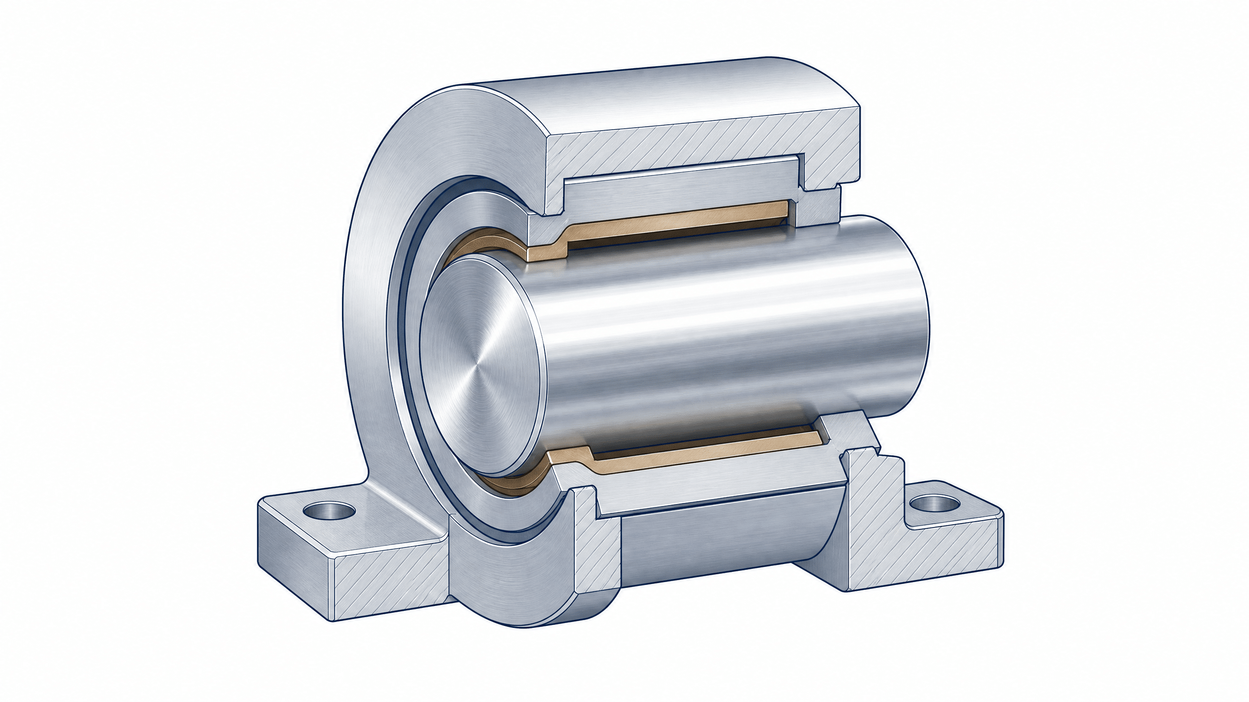
Four surfaces matter for a bushing assembly, and each carries its own limit:
- Bore (ID) tolerance — the finished inner diameter. For wrapped or thin-wall types the bore is made slightly larger in the free state so that it closes to the target value once the housing clamps it during pressing.
- Shaft tolerance — the journal the bore runs against. The bore–shaft pair sets the running clearance.
- Bushing OD tolerance — the outside diameter that seats in the housing. For thin-wall and wrapped bushings this is typically oversized to create a press fit.
- Housing bore tolerance — the machined pocket in the mate. The bushing-OD / housing-bore pair sets retention.
Concentricity between bore and OD also matters: a bushing that seats true keeps the running clearance even around the circumference. Out-of-round or taper in any of the four surfaces shifts load to a narrow contact band and shortens life.
Clearance, transition, and interference fits
Fits fall into three families, named by how the shaft/hole limits overlap:
Clearance fit
The shaft is always smaller than the bore. Used where the journal rotates or oscillates and a film must be maintained. The running clearance is set by the chosen grade pair (for example H7/g6); for the lubrication path that supports that film, see grease groove design.
Transition fit
Limits may overlap slightly; the result is a light location that can be assembled by light press or push. Common for locating a bushing that should not move axially under load
(for example H7/k6).
Interference fit
The shaft (or bushing OD) is larger than the mating hole; assembly needs force or a temperature differential. Used to retain thin-wall and wrapped bushings in the housing so they cannot turn or walk (for example H7/p6 or H7/r6 on the OD side).
For plain bearings the bore–shaft pair is usually a clearance or transition fit, while the bushing–housing pair is often an interference (press) fit for thin-wall types or a transition fit for thick-walled cast bushings.
Typical bore (ID) limits — ISO 286 H7
The bore of a machined cast bronze bushing is most often finished to H7. The upper deviation (the “+” value) grows with diameter; the lower deviation is 0. Values below are typical H7 upper limits — confirm against ISO 286 and the drawing. For a full ID/OD/L reference by series see the bushing size chart; for thrust washers the same H7 convention applies to ID and OD, with thickness as a third dimension — see the thrust washer size chart.
| Nominal bore (mm) | H7 upper deviation (µm) | Lower deviation |
|---|---|---|
| up to 10 | +15 | 0 |
| 10 – 18 | +18 | 0 |
| 18 – 30 | +21 | 0 |
| 30 – 50 | +25 | 0 |
| 50 – 80 | +30 | 0 |
| 80 – 120 | +35 | 0 |
| 120 – 180 | +40 | 0 |
| 180 – 250 | +46 | 0 |
OD press-fit allowance: wrapped and thin-wall bushings are supplied with an OD larger than the housing bore by a small, specified allowance (per ISO 3547 / DIN 1850 / GB/T 23894). That interference, not a clearance, is what holds them in place. Thick-walled cast bushings may instead use a transition fit and a retention feature such as a pin or flange.
Common shaft and housing fit pairings
| Fit (hole/shaft) | Type | Typical use for plain bearings |
|---|---|---|
| H7/g6 | Clearance | Rotating shaft at moderate speed; maintains a lubricant film. |
| H7/h6 | Clearance (sliding) | Low-speed, oscillating, or indexing motion. |
| H7/k6 | Transition | Locating a bushing that must stay axially fixed under load. |
| H7/p6 – H7/r6 | Interference | Retaining thin-wall / wrapped bushings in the housing OD. |
The same letter system applies on the housing side: the bushing OD is the “shaft” of that pair. A wrapped bushing sized H7/p6 against th
e housing bore will be pressed in; the inner H7/g6 or H7/h6 then governs the running clearance against the journal.
Selection by duty
| Condition | Fit tendency | Reason |
|---|---|---|
| Heavy load, low speed | Tighter location (H7/k6), adequate clearance | Keep the journal centred; avoid edge loading. |
| Higher speed | Confirmed clearance (H7/g6) | Room for the film and thermal growth. |
| Large thermal swing | Extra clearance | Shaft and housing may expand at different rates. |
| Soft housing (aluminium) | Controlled interference | Prevent the bushing from turning in the pocket. |
Five-step path
- 1. Fix the duty: load direction, speed, temperature range, and motion type.
- 2. Choose the bore fit from the running-clearance need (H7/g6 or H7/h6 typical).
- 3. Choose the housing fit from retention need (transition for thick-wall, interference for wrapped).
- 4. Check thermal growth and housing material against the chosen clearance.
- 5. Confirm every limit against the drawing, ISO 286, and the supplier’s specification.
If you already have measured sizes from an existing assembly, use search bearings by dimensions to match a part before setting the fit.
Standards you will meet
Most bushing drawings reference a small set of standards, and knowing which one governs which dimension prevents mismatch:
- ISO 286 — the IT grade system and the H/g/h/k/p/r hole-and-shaft letter pairs used in the tables above.
- ISO 2768 — general tolerances for dimensions not individually specified; it does not replace a named bore fit.
- ISO 3547 / DIN 1850 / GB/T 23894 — wrapped (Bundbuchse) bushing dimensions and the OD press-fit allowance; for the linear and guide formats see the slide bushing size chart.
Graphite-plugged cast bronze bushings are usually machined to the same H7 bore convention, then drilled and plugged. Cast bronze is the base material for many of these parts because its dense, machinable matrix holds the bore geometry and the graphite plugs that carry solid lubricant. For alloy notes by duty see material selection for high load; for a copper-based grade cross-reference see copper-based alloy selection.
Fit selection by duty, not by catalog
For industrial machinery, construction equipment, and agricultural machinery, the fit should follow the load path rather than a single catalog value:
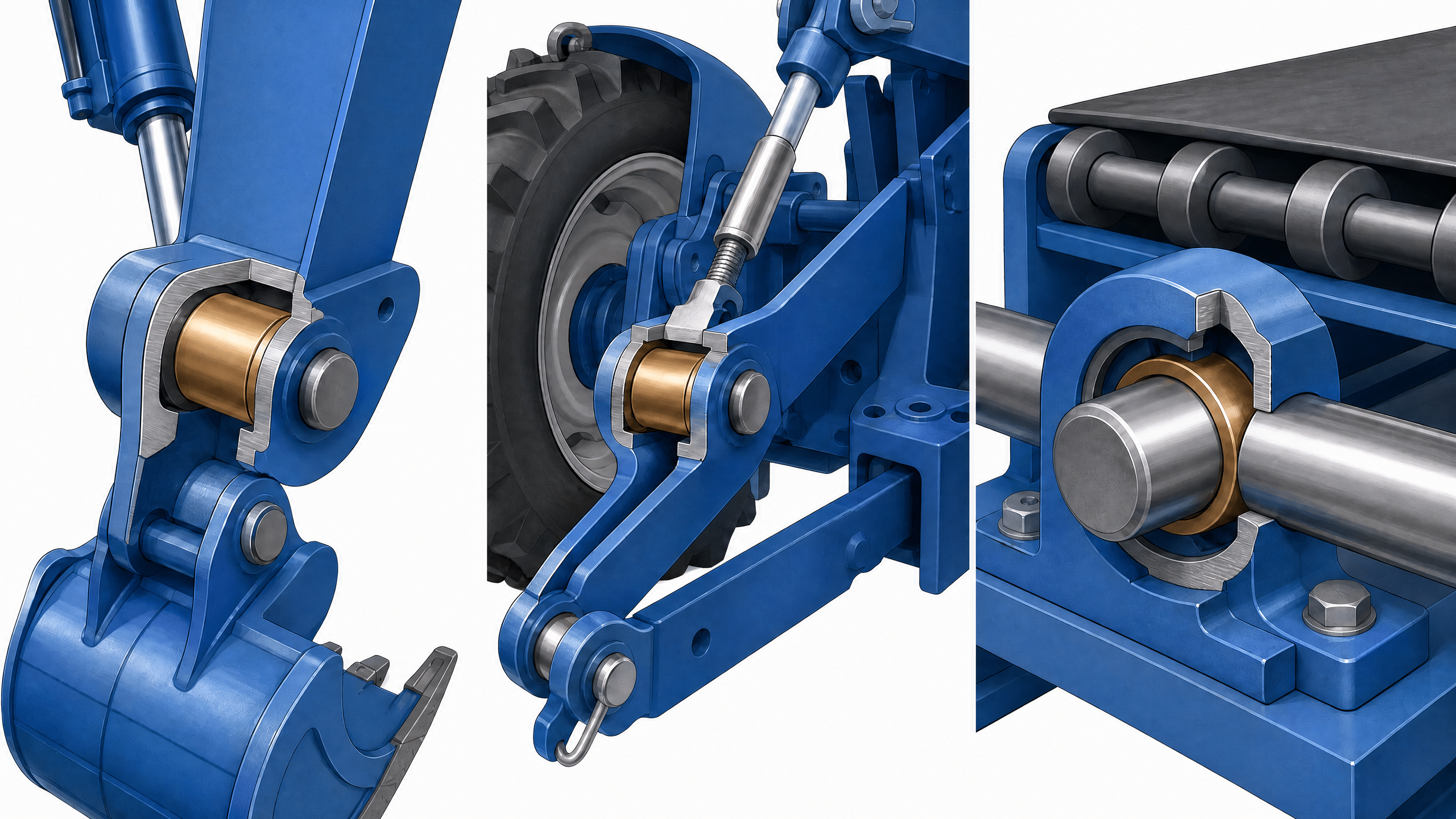
- Construction and agricultural joints — heavy, shock-loaded, often lower speed. A located bore (transition fit) with enough clearance to keep the film avoids edge loading when the joint sees side load.
- Continuous industrial drives — steady speed and load. A confirmed clearance fit supports a stable film and accommodates thermal growth.
- Housing material — a soft aluminium pocket needs a controlled interference so the bushing cannot rotate; a cast-iron or steel housing can use a lighter retention.
Where the part runs hot or the shaft and housing use different materials, add clearance for growth so the running gap does not close. These notes cover general industrial selection; they are not a substitute for checking the specific assembly.
Housing material: setting fits for aluminium housings
Aluminium housings appear wherever weight matters — marine hardware, deck equipment, gangways, hatch and door gear, and general machinery. They behave differently from steel or cast iron in three ways: the alloy is more compliant, it expands more per degree, and it sits on the anodic side of copper alloys in the galvanic series. Each of those changes how a fit should be specified.
Interference in a compliant housing
Because aluminium yields more than steel, the usable interference window is narrower. An interference that grips safely in a steel bore can generate high hoop stress in an aluminium bore, especially where the wall is thin or interrupted by ribs, ports, or bolt lugs. The fit is normally selected toward the light end of the interference range and then checked against the actual wall geometry. Where the section is thin, retention is often shared with a flange, a retaining compound, or a locking feature rather than carried by interference alone. Specifying the housing alloy and temper on the inquiry matters here — “aluminium” is not a specification.
Thermal expansion across the service range
Aluminium alloys expand more per degree than copper alloys. Representative values are roughly 21–24 ×10⁻⁶/°C for aluminium and 16–19 ×10⁻⁶/°C for tin, aluminium, and manganese bronzes; confirm the figures for the alloys being used. Because the housing grows more than the bushing, grip relaxes as temperature rises and tightens as it falls. The change in diametral interference can be estimated with:
ΔD = D₀ × (α_housing − α_bushing) × ΔT
Check both ends of the range. A fit that holds at room temperature can become a slip fit at the upper limit, and the same fit can overload the housing wall at the lower limit. Assemblies built indoors and shipped to a colder climate are a recurring source of this problem, as are joints that see direct sun on one face.
The bore after pressing
Pressing closes the bore. The amount depends on wall thickness, alloy stiffness, and the actual interference, so it is treated as a measured result rather than a constant. Where running clearance is tight, the practical route is to plan a finishing operation after installation — reaming, boring, or burnishing the ID to its final size — instead of predicting the closure and machining the bushing undersize in advance. State on the drawing whether the ID tolerance applies before or after installation; leaving this open is a common cause of assembly disputes and of bushings that run stiff on first start.
Galvanic risk at the bore interface
Copper alloys are cathodic to aluminium. Where an electrolyte is present — seawater, salt spray, or water held in the bore — the aluminium at the interface corrodes preferentially. The consequence is mechanical rather than cosmetic: material loss at the bore reduces the interference that retains the bushing, and the corrosion products occupy more volume than the metal they replace, which can distort the bore or lock the bushing in place. Risk is highest where water is trapped, such as blind bores, horizontal pivots, splash-zone
joints, and assemblies that are washed down but not drained. Mitigation is design-specific and usually combines drainage and sealing, isolation of the two metals where the design allows it, a housing surface treatment suited to the exposure, and alloy selection verified against the service environment.
Failure pattern to cause
| Observed condition | Cause to investigate |
|---|---|
| Bushing turns in the housing | Interference too light; grip lost to thermal growth at the upper service temperature; bore enlarged by corrosion |
| Excessive play at the pivot | Running clearance too large for the duty; bore wear from abrasive ingress; ID oversize after press-fit finishing |
| Shaft turns stiffly or seizes | Bore closed more than expected after pressing; insufficient clearance for the temperature range; corrosion product at the bore |
| Housing cracked at the bore | Interference too heavy for the wall thickness; no lead-in chamfer; bushing driven in out of alignment |
| Bushing will not seat fully | Housing bore undersize or out of round; burrs; interference above the available press force |
These notes address fit and housing interaction. Alloy choice, groove pattern, and solid-lubricant options are separate decisions — see the bronze bushing overview for the surrounding selection picture. Corrosion behaviour depends on the specific alloy pair, the electrolyte, temperature, and how often the joint is wetted; treat it as a design review item and validate against the actual duty.
Frequently asked questions
What tolerance is a bronze bushing bore?
Most machined cast bronze bushings are finished to H7 on the bore. Confirm the exact grade and the installed (not free-state) value against the drawing.
H7/g6 or H7/h6 — which one?
H7/g6 gives a clearance suited to a rotating shaft; H7/h6 is a sliding fit for low-speed or oscillating motion. Pick from the running need, then check thermal growth.
Do wrapped bushings need a press fit?
Yes. Thin-wall and wrapped types use an OD oversize against the housing (interference) so they seat without turning. The inner H7/g6 or H7/h6 then sets the running clearance.
How much clearance is enough?
It depends on load, speed, and temperature. Use the fit tables as a starting point, then confirm against the duty and the supplier’s specification.
Can ISO 2768 cover the bore?
No. ISO 2768 is for dimensions not individually toleranced. The bore needs a named fit such as H7; 2768 does not set running clearance.
Do aluminium housings need a different press fit?
Generally yes. Aluminium is more compliant than steel or cast iron, so the interference is usually taken toward the light end of the range and checked against wall thickness. The housing alloy and temper should be stated on the inquiry, and the fit should be checked across the full service temperature range because aluminium and bronze expand at different rates.
Why does the bore change size after pressing?
Pressing a bushing into a smaller housing bore compresses the bushing wall, and the inner diameter closes. The amount varies with wall thickness, alloy, and the actual interference, so the reliable approach for tight clearances is a finishing operation after installation — reaming, boring, or burnishing the ID to its final size — rather than predicting the closure in advance. State on the drawing whether the ID tolerance applies before or after installation.
Build the full selection picture
This guide covers tolerance and fit. For the surrounding decisions, see the bronze bushing overview, the sleeve bushing types, and the brass sleeve bushing reference. Sizing tables for specific forms are linked in the sections above.


